1 and 2 of this Page is an
extension of Erwin's SG Work Shop
Image
1, is
my
very first SSG Replication.
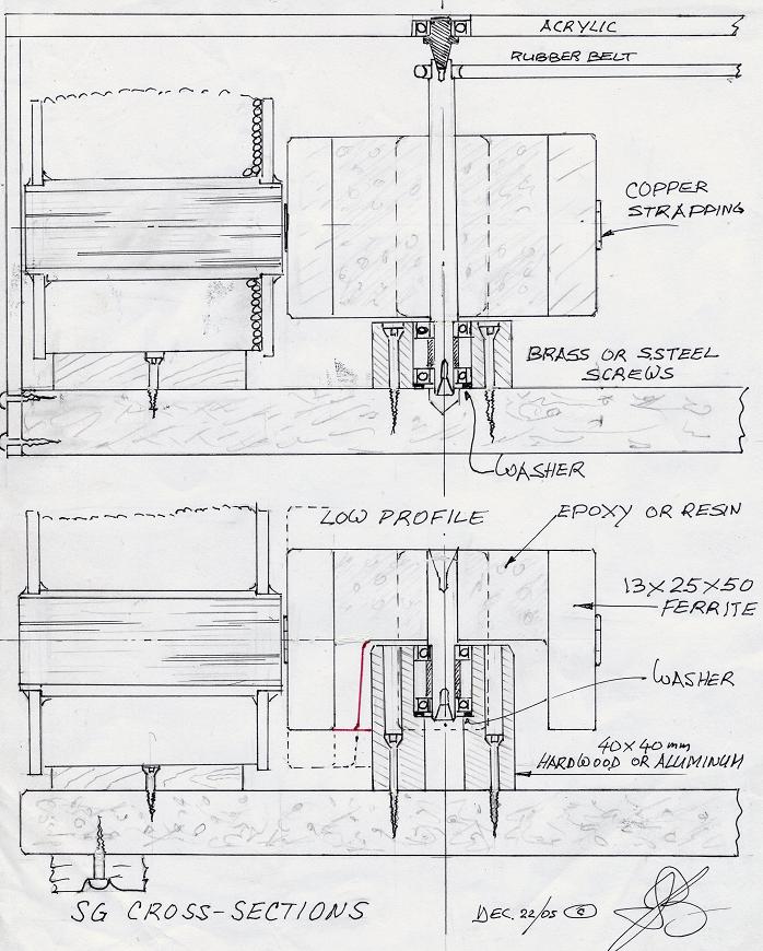
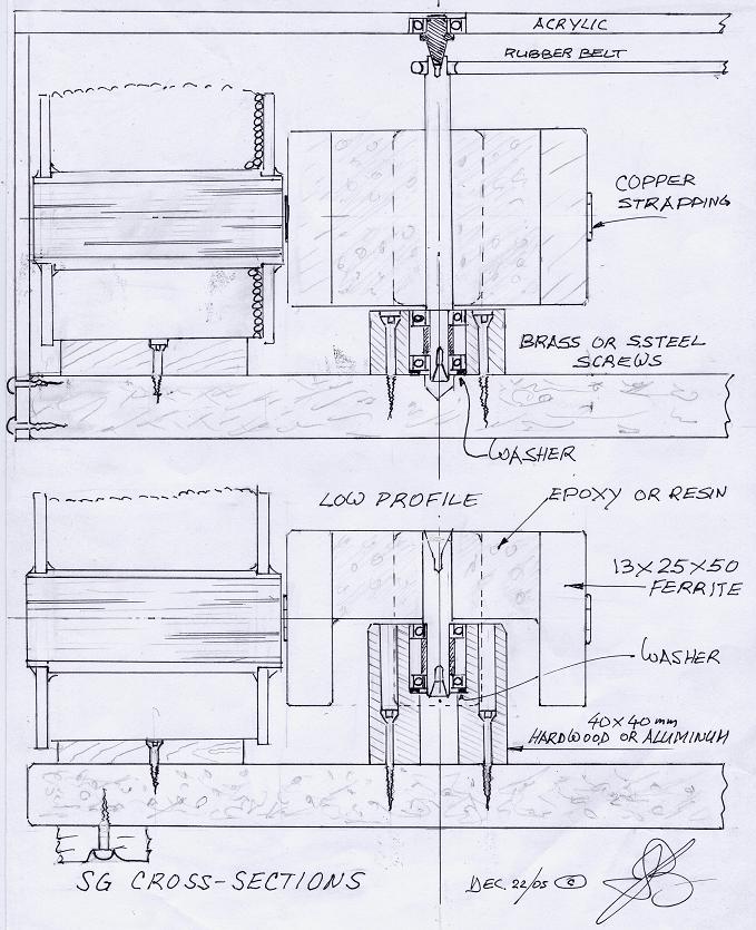
I started with a 2 1/2" fiberglass rotor on a floppy disk base and a floppy shaft with the magnets running close to the level of the bearings, thus a low center of gravity design emerged, making it unnecessary for a shaft protruding out the top supported by a bearing (less work), using 1/8x5/8x3/4 magnets rapped with reinforced packing tape....very important for safety otherwise a magnet will depart with a big bang, soon or later. In fact, I use copper strapping to hold them tight to my rotors, I use glue on the mags to keep the strapping there for good. I haven't lost any flying magnets since. I suggest for serious builders to start with 13 x 25 x 50's tapered like a swallow tail, right off the bat. I cut the 10 to 15°
Image 1 click on all my pictures and drawings
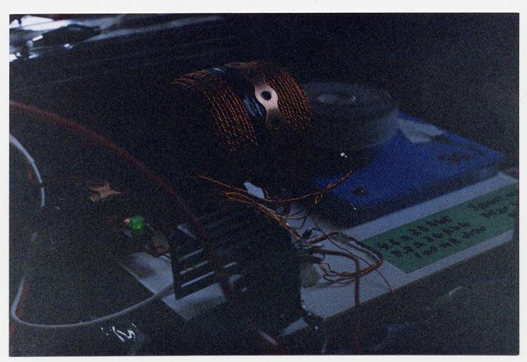
The coil I built with 200 ft 5 filer magnet wire, one #26 AWG trigger and 4 #23 AWG drive windings with an LED in parallel --> anode on pos. and cathode on the negative side of the coil. Reed Shop Talk for proper coil set up instructions.
For coil core material John Bedini uses Lincoln R60 AWS R60 Diameter (in) 1/16 Diameter (mm) 1.6 . He is also suggesting cast iron core. I used 1/16 tie wire in a 1 inch core, annealed and lacquered, annealing is heating up the steel to a red hot temp. removing from the wood coals or other heat and let cool down slowly on a heated fire brick. Because of forgetting to set the proper exposure opening the picture is a little on the dark side, (click on it). In the picture's (my only one) foreground you can barely see (might have to squint a bit) the aluminum heat sink inside which I had used a 2N3055 transistor. I hope you can see the LED lit on the left. The 1/2" 22 GA. copper strapping I use on my coils is easy and quick to work with, what I like best about it; no need to build complicated coil assembly brackets. You get it at plumbing whole sales stores or at http://www.dahlvalve.com/
Image 2

Here you can see the remainder of a floppy base bolted down to copper tubing with two brass screws. The rotor shaft is 4mm running in one steel bearing and a lower bronze bushing. Because the magnets where less than 1 1/2 their width apart from each other, I was hardly able to start the rotor by hand, but a good pull-start with the string would do the trick.
This might sound very casual, but I tell you, I was ready to drive my hat into the ground... could not understand why this little 2/1/2" critter would spin up so hard! Not until I build a 4" rotor (image 3 below) which spun up at once with a little nudge, aah... only then did I realize with confidence that a string surely would do the trick.
The four BD243C transistors I used as a test bed for studying all different kinds of switching combinations to learn the behavior and different sounds (using my acoustic tester) of transistors in their settings, which helped me since a number of times, to find causes to problems. Look at my transistor set up and notice, if I wouldn't have looked so far, I could have had the proper six coil switching (Icehouse) then already, all I had to do is, connect the bases and take the four wires and bolt them to the collector plate!! dahhh....I guess my mind had to much Andreatta rocket thrust....
On start up, or if something is wrong with the SG, you'll find quickly what you are looking, or not looking for, ha…. by the kind of sound or no sound the tester makes!
The yellow capacitor in the foreground is not hooked up in this picture. Only use wire wound potentiometers, the others suffer burn spots from the high voltage spikes. The "on" and "off" switch in the back ground I also salvaged out of a monitor. The red and blue pos. and negative auto wires are No. 8. All the negative lines leaving my machines are hooked to a copper ground rod with cable before leading back to the batteries, likewise are some of my positive cables, which I am testing at the moment, Aluminum No. 3 conductor on top of 10 ft posts into the batt. positive with a 1N4007 and Neon bulb. The copper coil commercially used rapped around monitor tubes, make good negative bus lines leading to ground from my machines I've used lately.
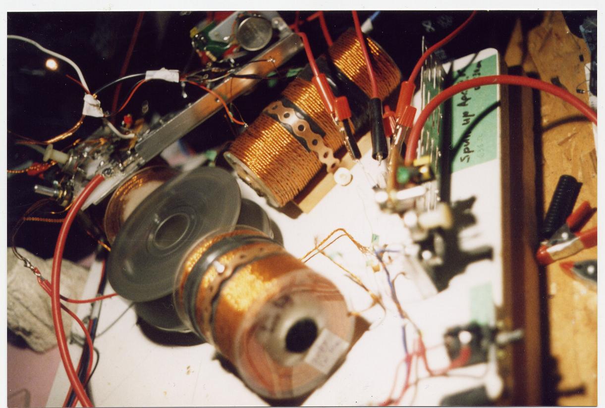
Here I was measuring the difference of the standard size to a long and skinny coil. For this purpose the long one did not pan out. Suffice to say is that this trio did fix up one of my dead (1Volt) 2V cells, here is the story:
Some time back I Bought this old huge VARTA Industrial 18 cell battery, which was on the way to the scrap yard, at a battery dealer for 50.- bucks. The cells came tightly fitted in a 3/16 inch (5mm) steel plate container, measuring 400x730x960mm or 15 ¾ x 28 ¾ x 37 ¾, could barely lift it with our John Deer farm tractor! The cells are approx. 5” square by 3 feet tall and are equipped with connecting cables thicker than my thumb.
Image 4

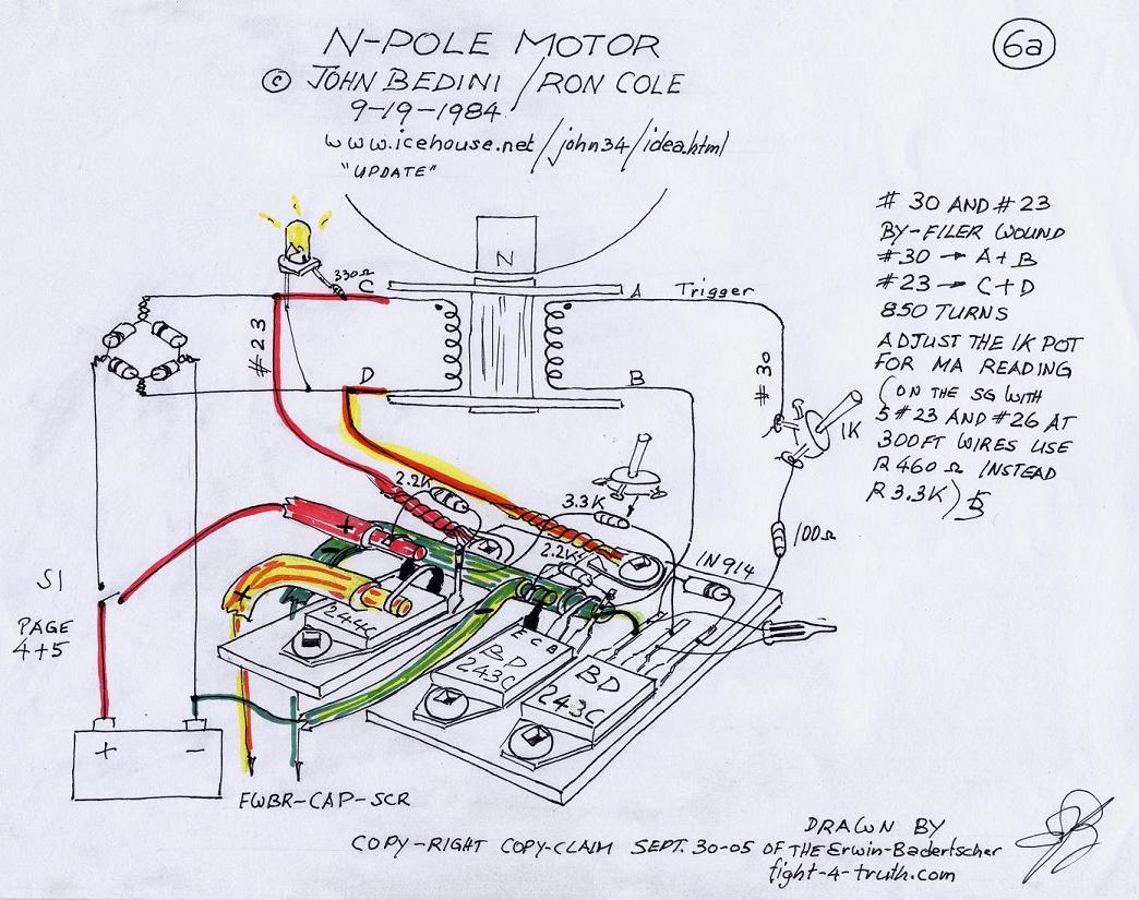
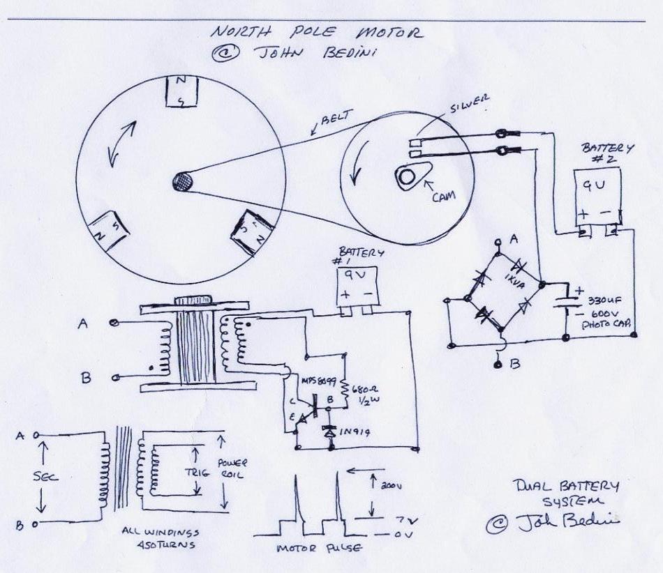
This next SSG Bedini/Cole N-Pole Motor of course is my pride and joy, it is a big leap in the success of my Bedini technology research. There is real bronco performance in the Bedini designs. I am very happy I got into it, I learned a lot already in a very short time and especially in a field I was totally ignorant in. This knowledge gained will make me more flexible in my approach for alternative power.
The switching is illustrated in the blueprint page Images 6 to 8.
As you can see by the wire color, the NPN collector plates are negative where as the PNP plates are positive. Interestingly the frequency of the NPN-plate (trigger) is the usual low whereas the PNP plate indicates pitch one octave higher. Other builders seam to use transistor grease and insulater pads between the transistor base plate and heat sink. I do the opposite and use silicone grease as a good conductor which is working just fine for me. Compare "N-Pole-Motor-6a,.jpg " or "N-Pole-Motor-6b,.jpg" to "B&C N-Pole Motor update" or "SSG4a heat sink" image 6a below.
Tuning a multi coiler
First I test every coil for the Ohm value, should be all the same if the wires are all cut to the same length, they must all be the same if one wants top performance. Then I strap one down in a single set up with 10 ohm 2 watt resistor and 250 ohm 25 watt wire wound rheostat usually with a neon lamp and LED. Once I have the rotor running in the sweet spot, which is the highest RPM and lowest current draw off the primary PS (power source) watching with the VOM the charging voltage going into the batteries, holding a clamp ammeter around one charging lead then slowly cranking my rheostat or pot , towards the lowest possible ampere reading going into the batts, all the while watching the charging voltage which is usually lowest (in and out) at the sweet spot, here I play with the gap setting a bit, then I turn the pot into the direction where I get the quickest and most charging voltage without changing the current draw, here too I play with the gap setting a bit. Then I measure the VAC off the coil which is usually between 9 and 13 volts pending on the number of turns on the coil. I also mark down the charging voltage across the SCR or SCR anode and batt. negative (before and after). After shut down I mark down the gap setting, (the coils must have all the same settings in a multi coil arrangement). Thereafter I measure the ohm value from the pot to the transistor base and install resistors with the same value onto all other coils. Sometimes I use a single pot and adjust the ohm setting as I add coils, other times I do not bother with any. My little SSG4a (300feet of 1 #26 awg 5 #23 awg/coil) I don't need to adjust, has no pots and is a real performer. It will charge up a 600CCA batt from 12.25 to 14.2 volts in approx.1/2 an hour, fed by my 15V variable PS!
The strapping is very much needed on the rotor, besides it makes no difference to the charging performance what so ever. The collector plates (heat sinks) on top of the left coil are my test plates for polarity orientation. You have to remember I had no schooling and very little advice in this field and some of the basic facts you just can't find in any books, hence I find myself around the rest by trial and error common sense and mainly the Lord's help. What's hanging off the side on the left of the capacitor is a RURG 80100-ND diode instead a charging cluster of 1N4007's, it dropped the driving current by 0.3ma before I used the SCR. The neon lamp I check for more than 60V potential.
Image 6
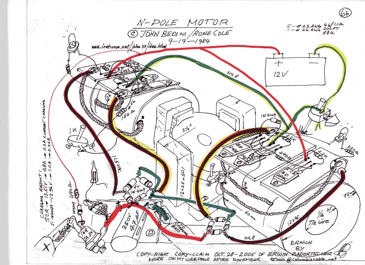
I am very pleased with this SSG4a and the whole set up. I can watch the 1/100 volt increments rising every 5 seconds through the whole charging cycle at a 15V 3amp input 0.8 amps out - 600CCA batt. The spinner of this machine has a "yogurt" rotor with a 4 mm shaft, this rotor really winds up, considering it being plastic, to say the least. Course because of the 2" leverage I used a life center in the top bearing to keep it steady , by using the acrylic strip. Keep in mind that acrylic is very brittle, vibration in the machine will make it crack. Go extra heavy or don't use it at all. Tolerance is pending whether the rotor is running below center or not (right along the cross section plan see energizer rotor base). Much simpler than sliding the bearing over the shaft, plus it is easier creating play and guiding the rotor shaft without placing side pressure on the rotor, since we have a two bearing assembly below (all we need is a little support) . I used of course the same Bedini/Cole switching (Imaga 6a below) as my prior SG6b or B&C N-Pole Motor update and #8 Automotive wire on the buses with 4 photo caps 330V 100uF in parallel, 3 home made parallel 1000V FWBR's and my usual 16 Amp 800Volt Thyristor (16RIA80) with an R330 and 1N4007 lead bias gated. I was pleased that the safety neon (positioned at 10:30 o'clock under the big negative wire) bailed me out a wile back, when the SCR did not conduct at a start up charging operation (For the same reason I use an LED with a 330 Ohm 3Watt resistor in parallel when charging small batts), with my 15V power source primary in, charging a 5 Battery bank 1000CCA each (Cold Cranking Amps), which made me realize that the bias conductor was to long. Look at image 5 where you will see a white long wire on the right side off the resistor from the SCR. The wire should be very short connecting to the positive of the FWBR. I took the commercial board out of the battery charger and replaced it with my own wires and re hooked the LED's for 2 9V's, 2 or 4 -1.25V NiCad’s. For photo purpose I used my 2.5Amp 11.6V out, Desktop Power Supply with the Happy Day Goat Dairy wind tunnel ------->Warning! If there are children around do not use this kind of set up, usually I use the variable PS. I don't recommend you hooking up this small size of an energizer to a big industrial 2V deep cycle cell for example, it will be a poor impedance match, if you do , check the trigger wires since some might have broken off due to vibration (you won't know unless you physically check them) if so, the intake will climb to 5 A and so will the charging end, the BD243C's will be under rated, get hot and probably burn up.
Image 6a,
I am sure you could do a nicer soldering job on the transistor terminals, I am always in a hurry. The reason for the yellow conductor reaching so rudely across the table it had been hooked up along the back to the negative copper terminal before, the red conductor worked better I had to just move it a little bit to reach the collector transistor terminal. Those two trigger resistors in parallel in the foreground where used because one alone heated up, I din't have the right value at the time. I exchanged the three resistors with one 120 ohm 2 watt since.
Image 6b,
Here is a little different angle of my SSG4a jewel. It runs pretty near every day charging some battery anywhere from 1.25V to 18 V capacity type. Some batteries it charges are slowly gaining in holding capacity be they old or new.
Rescuing an old sulphated 1000 CCA battery by cycling it my way:
A friend looked for a spark by striking a wire between the two terminals of a 12V battery in a scrap yard and brought it to me. It is called a freedom battery and had removable pry caps under the plastic sticker, thus I was able to top up the electrolyte, the ones which have no removable caps are garbage (rip off).
The idea is to place a load of 5.2A onto the battery for a short duration while making sure the battery recuperates over 12 volts, preferable 12.25V.
The Hydrometer showed a 0.1125 density of the electrolyte reading and the voltmeter indicated 11.25 Volts and the conventional charger accomplished zero charging.
I hooked it up to my SSG4a with a Volt reading of 11.28 and climbing, which is a promising sign. (Usually the initial charging with old sulphated no good batts is between 18 and 24Volts with the voltage slowly dropping to the proper level where it then starts climbing). When the battery was to the point where the volt needle no longer climbed any further I discharged it with two car tail light bulbs at 5.2 A within a few seconds, watching the voltmeter needle dropping to 11.5V then letting it recuperate. If it recuperated more then to 12.25V, I discharged it a little more. You want to make sure it always recuperates over the 12.00V mark. Next charge it would stop charging a little higher as before and would take a little longer to discharge and it also would recuperate a little more say, to 12.35V. In repeating the charging and discharging cycle, it became evident that the battery after 48 hrs cycle time would charge up to 14.75V and would discharge and hold a 5.2A load down to 12.10V for 15 min. by removing the load the battery would recuperate to 12.58V within 5min. I left it sit for a week or so, the volt indicator needle showed 12.50V and applied the same load to it. It held the load of 5.2A at 11.90V without dropping any further for 15 min. where I unhooked it and watched it recuperating to 12.30V within one minute. Of course I charged it up to max. voltage right away again. The more I repeat this cycle the more capacity the plates will store. I tried this with several batteries now and it seams to work according to the quality of the battery; very well for some and not so good for others. This system is a lot less time consuming than the procedure of the C20 rate.
Image 7,
I started with a 2 1/2" fiberglass rotor on a floppy disk base and a floppy shaft with the magnets running close to the level of the bearings, thus a low center of gravity design emerged, making it unnecessary for a shaft protruding out the top supported by a bearing (less work), using 1/8x5/8x3/4 magnets rapped with reinforced packing tape....very important for safety otherwise a magnet will depart with a big bang, soon or later. In fact, I use copper strapping to hold them tight to my rotors, I use glue on the mags to keep the strapping there for good. I haven't lost any flying magnets since. I suggest for serious builders to start with 13 x 25 x 50's tapered like a swallow tail, right off the bat. I cut the 10 to 15°
Image 1 click on all my pictures and drawings
The coil I built with 200 ft 5 filer magnet wire, one #26 AWG trigger and 4 #23 AWG drive windings with an LED in parallel --> anode on pos. and cathode on the negative side of the coil. Reed Shop Talk for proper coil set up instructions.
For coil core material John Bedini uses Lincoln R60 AWS R60 Diameter (in) 1/16 Diameter (mm) 1.6 . He is also suggesting cast iron core. I used 1/16 tie wire in a 1 inch core, annealed and lacquered, annealing is heating up the steel to a red hot temp. removing from the wood coals or other heat and let cool down slowly on a heated fire brick. Because of forgetting to set the proper exposure opening the picture is a little on the dark side, (click on it). In the picture's (my only one) foreground you can barely see (might have to squint a bit) the aluminum heat sink inside which I had used a 2N3055 transistor. I hope you can see the LED lit on the left. The 1/2" 22 GA. copper strapping I use on my coils is easy and quick to work with, what I like best about it; no need to build complicated coil assembly brackets. You get it at plumbing whole sales stores or at http://www.dahlvalve.com/
Image 2
Here you can see the remainder of a floppy base bolted down to copper tubing with two brass screws. The rotor shaft is 4mm running in one steel bearing and a lower bronze bushing. Because the magnets where less than 1 1/2 their width apart from each other, I was hardly able to start the rotor by hand, but a good pull-start with the string would do the trick.
This might sound very casual, but I tell you, I was ready to drive my hat into the ground... could not understand why this little 2/1/2" critter would spin up so hard! Not until I build a 4" rotor (image 3 below) which spun up at once with a little nudge, aah... only then did I realize with confidence that a string surely would do the trick.
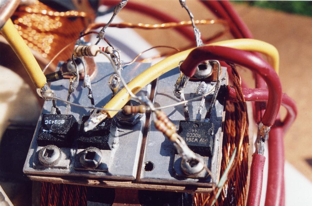
The four BD243C transistors I used as a test bed for studying all different kinds of switching combinations to learn the behavior and different sounds (using my acoustic tester) of transistors in their settings, which helped me since a number of times, to find causes to problems. Look at my transistor set up and notice, if I wouldn't have looked so far, I could have had the proper six coil switching (Icehouse) then already, all I had to do is, connect the bases and take the four wires and bolt them to the collector plate!! dahhh....I guess my mind had to much Andreatta rocket thrust....
On start up, or if something is wrong with the SG, you'll find quickly what you are looking, or not looking for, ha…. by the kind of sound or no sound the tester makes!
The yellow capacitor in the foreground is not hooked up in this picture. Only use wire wound potentiometers, the others suffer burn spots from the high voltage spikes. The "on" and "off" switch in the back ground I also salvaged out of a monitor. The red and blue pos. and negative auto wires are No. 8. All the negative lines leaving my machines are hooked to a copper ground rod with cable before leading back to the batteries, likewise are some of my positive cables, which I am testing at the moment, Aluminum No. 3 conductor on top of 10 ft posts into the batt. positive with a 1N4007 and Neon bulb. The copper coil commercially used rapped around monitor tubes, make good negative bus lines leading to ground from my machines I've used lately.
Here I was measuring the difference of the standard size to a long and skinny coil. For this purpose the long one did not pan out. Suffice to say is that this trio did fix up one of my dead (1Volt) 2V cells, here is the story:
Some time back I Bought this old huge VARTA Industrial 18 cell battery, which was on the way to the scrap yard, at a battery dealer for 50.- bucks. The cells came tightly fitted in a 3/16 inch (5mm) steel plate container, measuring 400x730x960mm or 15 ¾ x 28 ¾ x 37 ¾, could barely lift it with our John Deer farm tractor! The cells are approx. 5” square by 3 feet tall and are equipped with connecting cables thicker than my thumb.
Image 4
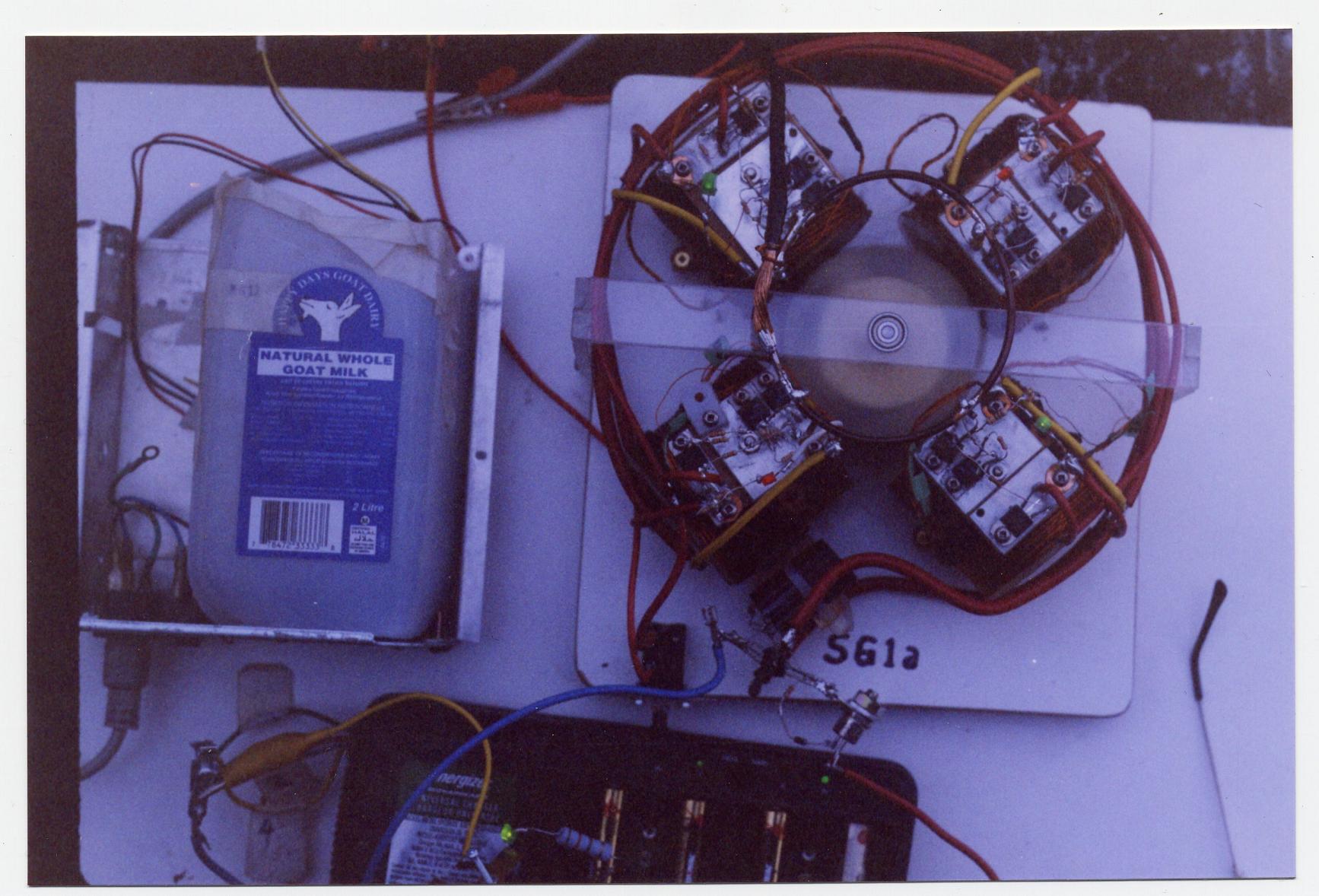
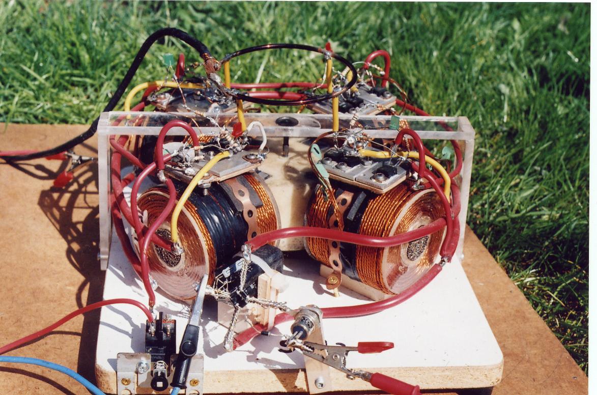
This next SSG Bedini/Cole N-Pole Motor of course is my pride and joy, it is a big leap in the success of my Bedini technology research. There is real bronco performance in the Bedini designs. I am very happy I got into it, I learned a lot already in a very short time and especially in a field I was totally ignorant in. This knowledge gained will make me more flexible in my approach for alternative power.
The switching is illustrated in the blueprint page Images 6 to 8.
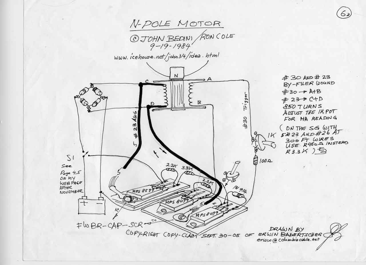
As you can see by the wire color, the NPN collector plates are negative where as the PNP plates are positive. Interestingly the frequency of the NPN-plate (trigger) is the usual low whereas the PNP plate indicates pitch one octave higher. Other builders seam to use transistor grease and insulater pads between the transistor base plate and heat sink. I do the opposite and use silicone grease as a good conductor which is working just fine for me. Compare "N-Pole-Motor-6a,.jpg " or "N-Pole-Motor-6b,.jpg" to "B&C N-Pole Motor update" or "SSG4a heat sink" image 6a below.
Tuning a multi coiler
First I test every coil for the Ohm value, should be all the same if the wires are all cut to the same length, they must all be the same if one wants top performance. Then I strap one down in a single set up with 10 ohm 2 watt resistor and 250 ohm 25 watt wire wound rheostat usually with a neon lamp and LED. Once I have the rotor running in the sweet spot, which is the highest RPM and lowest current draw off the primary PS (power source) watching with the VOM the charging voltage going into the batteries, holding a clamp ammeter around one charging lead then slowly cranking my rheostat or pot , towards the lowest possible ampere reading going into the batts, all the while watching the charging voltage which is usually lowest (in and out) at the sweet spot, here I play with the gap setting a bit, then I turn the pot into the direction where I get the quickest and most charging voltage without changing the current draw, here too I play with the gap setting a bit. Then I measure the VAC off the coil which is usually between 9 and 13 volts pending on the number of turns on the coil. I also mark down the charging voltage across the SCR or SCR anode and batt. negative (before and after). After shut down I mark down the gap setting, (the coils must have all the same settings in a multi coil arrangement). Thereafter I measure the ohm value from the pot to the transistor base and install resistors with the same value onto all other coils. Sometimes I use a single pot and adjust the ohm setting as I add coils, other times I do not bother with any. My little SSG4a (300feet of 1 #26 awg 5 #23 awg/coil) I don't need to adjust, has no pots and is a real performer. It will charge up a 600CCA batt from 12.25 to 14.2 volts in approx.1/2 an hour, fed by my 15V variable PS!
Image 5
Be patient with
this image after you click on it. Because of its size it
takes a bit longer for the expanding icon to appear.
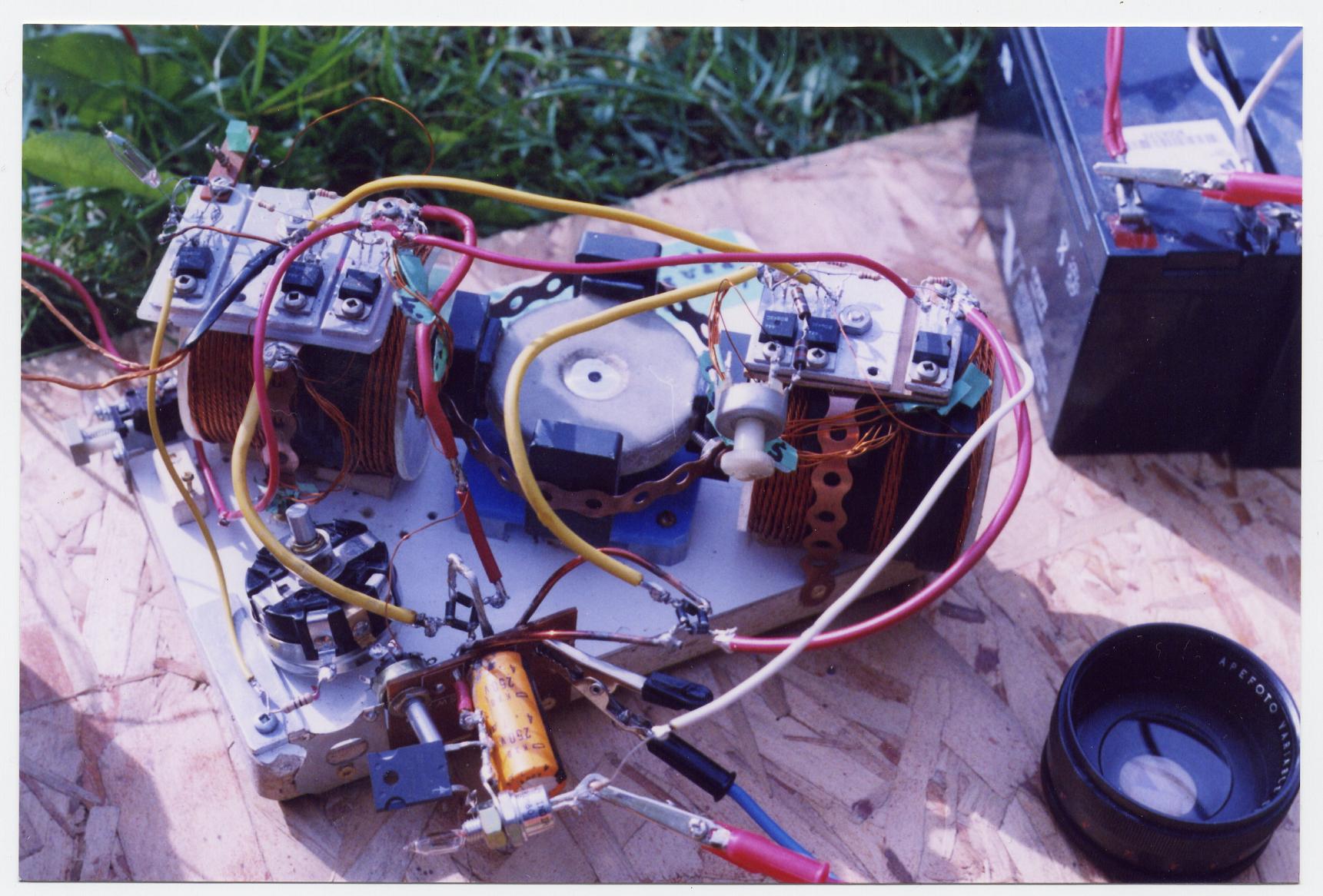
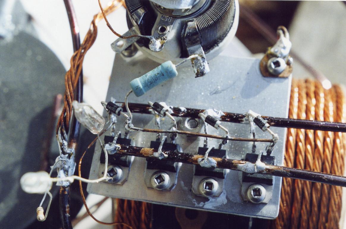
The strapping is very much needed on the rotor, besides it makes no difference to the charging performance what so ever. The collector plates (heat sinks) on top of the left coil are my test plates for polarity orientation. You have to remember I had no schooling and very little advice in this field and some of the basic facts you just can't find in any books, hence I find myself around the rest by trial and error common sense and mainly the Lord's help. What's hanging off the side on the left of the capacitor is a RURG 80100-ND diode instead a charging cluster of 1N4007's, it dropped the driving current by 0.3ma before I used the SCR. The neon lamp I check for more than 60V potential.
Image 6
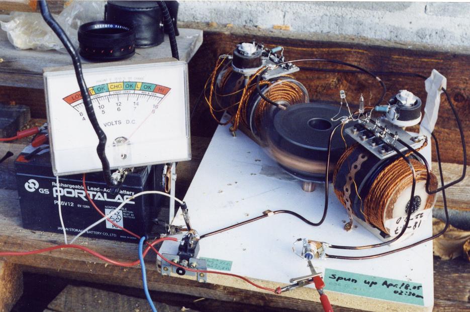
I am very pleased with this SSG4a and the whole set up. I can watch the 1/100 volt increments rising every 5 seconds through the whole charging cycle at a 15V 3amp input 0.8 amps out - 600CCA batt. The spinner of this machine has a "yogurt" rotor with a 4 mm shaft, this rotor really winds up, considering it being plastic, to say the least. Course because of the 2" leverage I used a life center in the top bearing to keep it steady , by using the acrylic strip. Keep in mind that acrylic is very brittle, vibration in the machine will make it crack. Go extra heavy or don't use it at all. Tolerance is pending whether the rotor is running below center or not (right along the cross section plan see energizer rotor base). Much simpler than sliding the bearing over the shaft, plus it is easier creating play and guiding the rotor shaft without placing side pressure on the rotor, since we have a two bearing assembly below (all we need is a little support) . I used of course the same Bedini/Cole switching (Imaga 6a below) as my prior SG6b or B&C N-Pole Motor update and #8 Automotive wire on the buses with 4 photo caps 330V 100uF in parallel, 3 home made parallel 1000V FWBR's and my usual 16 Amp 800Volt Thyristor (16RIA80) with an R330 and 1N4007 lead bias gated. I was pleased that the safety neon (positioned at 10:30 o'clock under the big negative wire) bailed me out a wile back, when the SCR did not conduct at a start up charging operation (For the same reason I use an LED with a 330 Ohm 3Watt resistor in parallel when charging small batts), with my 15V power source primary in, charging a 5 Battery bank 1000CCA each (Cold Cranking Amps), which made me realize that the bias conductor was to long. Look at image 5 where you will see a white long wire on the right side off the resistor from the SCR. The wire should be very short connecting to the positive of the FWBR. I took the commercial board out of the battery charger and replaced it with my own wires and re hooked the LED's for 2 9V's, 2 or 4 -1.25V NiCad’s. For photo purpose I used my 2.5Amp 11.6V out, Desktop Power Supply with the Happy Day Goat Dairy wind tunnel ------->Warning! If there are children around do not use this kind of set up, usually I use the variable PS. I don't recommend you hooking up this small size of an energizer to a big industrial 2V deep cycle cell for example, it will be a poor impedance match, if you do , check the trigger wires since some might have broken off due to vibration (you won't know unless you physically check them) if so, the intake will climb to 5 A and so will the charging end, the BD243C's will be under rated, get hot and probably burn up.
Image 6a,
I am sure you could do a nicer soldering job on the transistor terminals, I am always in a hurry. The reason for the yellow conductor reaching so rudely across the table it had been hooked up along the back to the negative copper terminal before, the red conductor worked better I had to just move it a little bit to reach the collector transistor terminal. Those two trigger resistors in parallel in the foreground where used because one alone heated up, I din't have the right value at the time. I exchanged the three resistors with one 120 ohm 2 watt since.
Image 6b,
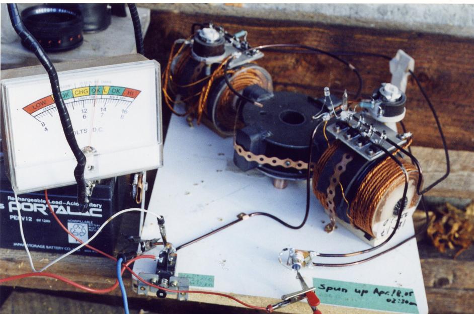
Here is a little different angle of my SSG4a jewel. It runs pretty near every day charging some battery anywhere from 1.25V to 18 V capacity type. Some batteries it charges are slowly gaining in holding capacity be they old or new.
Rescuing an old sulphated 1000 CCA battery by cycling it my way:
A friend looked for a spark by striking a wire between the two terminals of a 12V battery in a scrap yard and brought it to me. It is called a freedom battery and had removable pry caps under the plastic sticker, thus I was able to top up the electrolyte, the ones which have no removable caps are garbage (rip off).
The idea is to place a load of 5.2A onto the battery for a short duration while making sure the battery recuperates over 12 volts, preferable 12.25V.
The Hydrometer showed a 0.1125 density of the electrolyte reading and the voltmeter indicated 11.25 Volts and the conventional charger accomplished zero charging.
I hooked it up to my SSG4a with a Volt reading of 11.28 and climbing, which is a promising sign. (Usually the initial charging with old sulphated no good batts is between 18 and 24Volts with the voltage slowly dropping to the proper level where it then starts climbing). When the battery was to the point where the volt needle no longer climbed any further I discharged it with two car tail light bulbs at 5.2 A within a few seconds, watching the voltmeter needle dropping to 11.5V then letting it recuperate. If it recuperated more then to 12.25V, I discharged it a little more. You want to make sure it always recuperates over the 12.00V mark. Next charge it would stop charging a little higher as before and would take a little longer to discharge and it also would recuperate a little more say, to 12.35V. In repeating the charging and discharging cycle, it became evident that the battery after 48 hrs cycle time would charge up to 14.75V and would discharge and hold a 5.2A load down to 12.10V for 15 min. by removing the load the battery would recuperate to 12.58V within 5min. I left it sit for a week or so, the volt indicator needle showed 12.50V and applied the same load to it. It held the load of 5.2A at 11.90V without dropping any further for 15 min. where I unhooked it and watched it recuperating to 12.30V within one minute. Of course I charged it up to max. voltage right away again. The more I repeat this cycle the more capacity the plates will store. I tried this with several batteries now and it seams to work according to the quality of the battery; very well for some and not so good for others. This system is a lot less time consuming than the procedure of the C20 rate.
Image 7,
In
my temporary SG8 I did leave the switching arrangement
as
the standard SG, one transistor set up. I will see whether
soldering four transistors in parallel versus one, will really
make a
difference to the output (it did). I have rearrange into the SSG
because
I was
suppose to wind the motor and
trigger winding as a
two filler clock wise being a north pole (right hand rule), then on top
of that
I should have wound the power winding counter clock wise since it is a
south on
the north pole of that specific SG coil. See JB's
drawing "North Pole Motor for two batteries" regarding the dot
indicated polarity of the coils... Can't do everything right on the
first crack,
especially while flying by the seat of the pants. Well anyway,
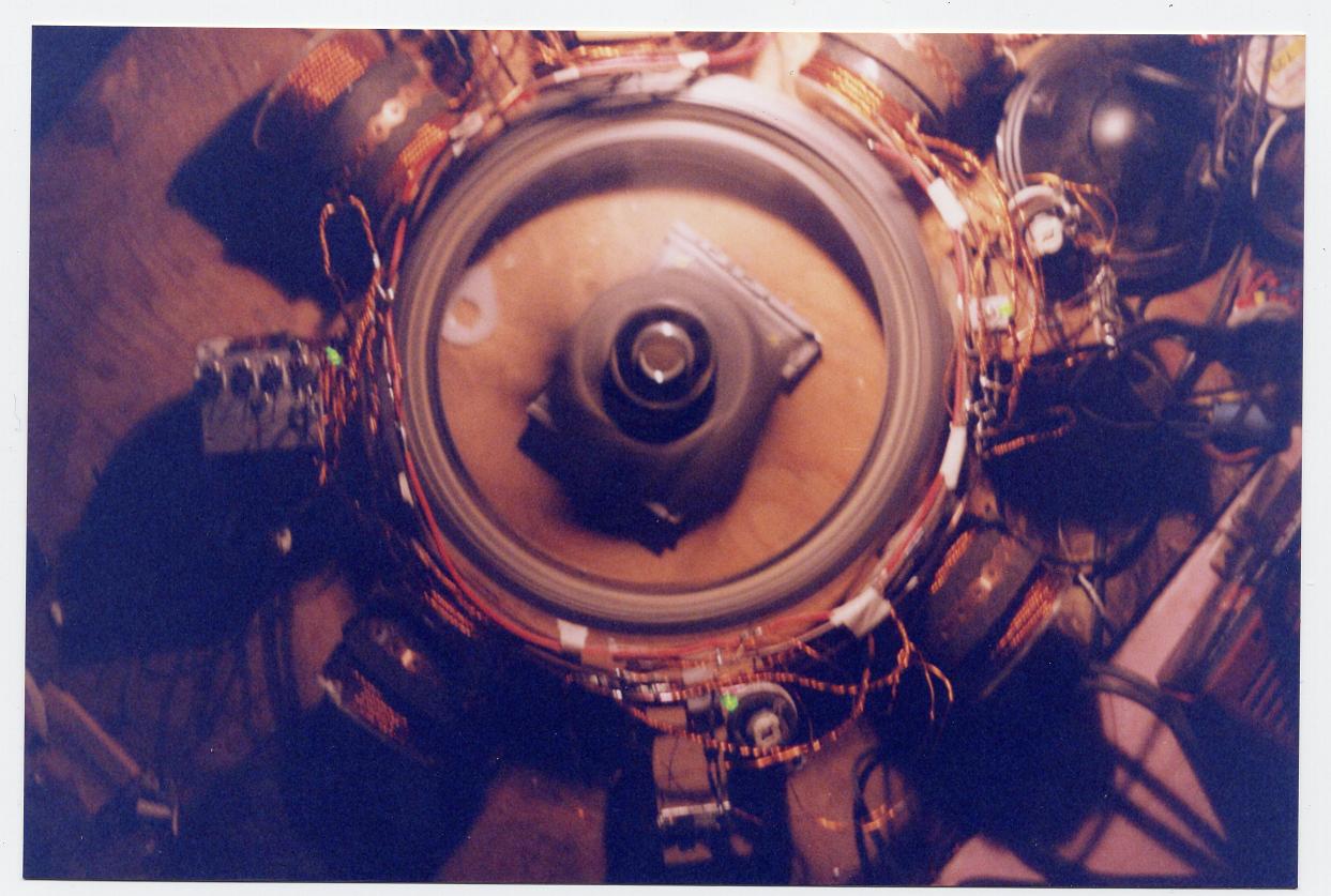
the difference was a pleasant surprise. The RPM in the photo of
this
picture is deceptive because of the long exposure timing used in the
camera, I
do not use flash, or tripods.
At first I had some trouble getting this cheap plastic rim up to speed because it was out of balance, besides the overall plastic spray cast is not of good quality being egg shape and warped. I clamped a 2"x6"x3ft board in the vice and mounted the bearing base radially and thus balanced it, which I accomplished by gluing #8 copper wires inside of the rim, I ended up sticking weights in three places because of the slightly different sizes of my 8 newly cut 1x1x4"mags. I used tape, then 5 minute epoxy and at the end a little quick set (E-Z).
The 1/2x2x2" mags I buried in a box as deep as I could, that way I won't get tempted to use them again!!
Now with the 4" mag's ----->15V 3.2Amps in, 0.9 Amps out charging an old 1000CCA Battery from 12.24V to 13.10V in 20 minutes (slow RPM) is not to bad for now, sure would like to have less current and more scalar energy going into the charging battery though. I changed everything into the SSG version, gaining one wire by collecting the back EMF off the collector, and also improving the scalar potential going into the batts (less current). Some time in the future I'll add some hard figurers once I acquired a scope (tried to do it with the computer but failed to succeed). Of course I'll set up proper buses like in my SSG4. These wires here are just temporary. I know, they are too close together too small and totally in the wrong place. I was not confident enough getting everything set up properly before, or if at all, I get this cheep plastic bicycle wheel in proper working order, time will tell. There is room to move the coils closer together, as you can see in the pic. meaning a smaller rotor, thus the buses would have been cut to the wrong length.
The coils are 150ft of 6 filer 5#18, 1#22 AWG twisted with an electric drill. 4 BD243C's one #8 wire is used to drive 8 coils in two's/parallel. Trigger wire bias is set at 45 ohm with a 1.8 ohm 2 watt resistor and 250ohm/25watt Power Rheostat wire wound. I noticed those big pots only get hot if something is wrong, a faulty connection somewhere close, for instance. The other 4 wires are used to collect the back EMF over 4 home made FWBR's in front of every twin coil arrangement soldered to # 8 magnet wire buses (not big enough) in a DC arrangement at the end through 5 100uF 330V photo caps in parallel and out the 16 amp 800V SCR.
Why running two coils on one transistor? When I had 4 coils1 transistor, SG style, 4 wires, one trigger, one drive winding, running on the base board , the motor was drawing a current of 4.6 amps with the 1/2x 2x2" mags! I quickly remembered the 10 year old running an added generator with a load (LED) also when I added a light onto two windings on the SSG2, the primary current dropped... thus I just added the next four coils in parallel to the same transistors to what I had so far and it did drop the intake current from 4.6 to 3.6 amps and when I added the bigger 1x1x4 mags, it went even down to 3.2 amps, telling me that the 2x2" wide mags where to wide and not tall enough, remember they are supposed to cover the whole face of the coil for max. performance!! The bearing arrangement is a CD set up. Those big magnets are of course too heavy for that assembly. I need to place a thrust bearing on the bottom end of it. I need to add a shaft out the top for a bearing and sheave or a big wheel for my cap timing anyway.
All my setups are usually connected to a good wet earth copper ground.
Switching the big six
Check out my new way of switching and changing over to the SSG and more, on page 3 Image 8.
The very short bus is the connection of the South Pole coil lead to the transistor plates (heat sinks) and one long bus bar is for the battery positive North Pole oriented lead of the coil, whereas the other two long bars are one positive charging bar off the transistor collector terminals and one negative bar off the emitter terminals below:
Image 8
Sorry about the saw dust on the assembly, was too much in a hurry that day. Yes you are right, there is a clear lacquer coating on this particular wire. I injured it on the pavement twisting it, pretzel time in the oven for 3HRS. This two coils are each 6 filer 1 # 22 /5 #18AWG for the five strands is 0.8 ohm at 150 ft, where 1 strand = 1.5 ohm.
Image 9
The two 6 V 7.2AH gel cell Batts in series showed a charge of 12.75V. I just gave the 4" rotor double stacked 50mm mags a quick (seconds) test run and as you can see below, they already rest at 13Volts. As above I had just enough time to take the picture before the volt indicator needle went out of sight!!!
Image 10,
Pass it on; it will be for the wellbeing of your own soul.
Last
update of this section: January 4, 07
http://www.fight-4-truth.com/Replication 1.html
:
COPY-RIGHT/COPY-CLAIM : DECEMBER ~19, 2005 BY
THE Erwin-Badertscher, OWNER OF THE ERWIN BADERTSCHER(SIC), TRADE-NAME.